Preface
Last week, I was working on redesigning my home network and this required some configuration changes to my ethernet switch, a Netgear GS110TP. I didn’t have the administration password handy as it was last configured many years ago. The unit has a straightforward password reset functionality which worked perfectly. While I was in there changing settings, I noticed that the firmware installed on it was quite ancient (dated 2010 or so) and that Netgear is still releasing firmware updates for this switch to this day. So naturally, I decided to update it.
Updating the switch is fairly straightforward, there’s an HTTP upload option in the web gui that lets you provide the firmware file. So, I downloaded the latest release from Netgear, read the release notes which basically just said to upload the firmware through the web gui and reboot, then installed the firmware into the second “slot” (flash partition). I then set that slot to “active” and rebooted the switch. To my surprise, the switch rebooted back into the old 2010 firmware. The web gui reported that the wrong “slot” was active and that this slot still had the old firmware in it. It also showed that the second slot had newer firmware in it. Re-setting the proper active “slot” and rebooting the switch would always just boot back into the wrong slot so I decided that I might as well just install the the new firmware into both slots (dumb thinking but I was getting pretty frustrated at this point since I’d just spent a few hours re-configuring the switch multiple times). Once I did that and rebooted the switch, to my demise, it would no longer boot and the status LED stayed amber permanently.
Unbricking the switch
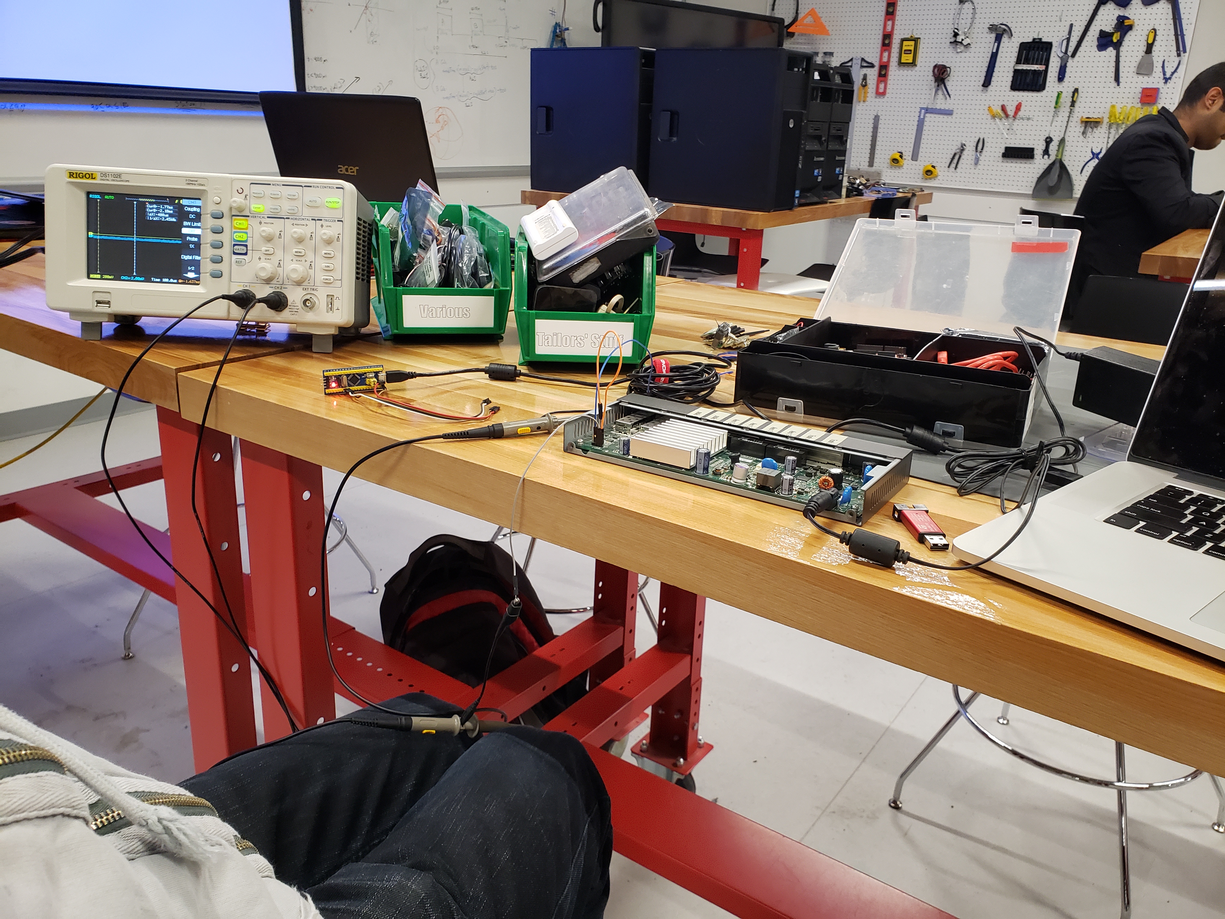
The first thing I did was unscrew the two rear screws and pop the lid off of the switch. Upon a swift inspection, I was immediately able to locate four pins with the word “CONSOLE” silk-screened next to them. Bingo! We’ve just located the completely undocumented console port. That was pretty easy! Now I’m not a very proficient reverse engineer so I looked up some tutorials on YouTube on how to identify the pins for a UART serial port on embedded devices. I needed a multimeter and an oscilloscope for the best results, both of which I didn’t have on hand. Luckily I remembered that that I could borrow such tools at my school’s library in the technology lab.
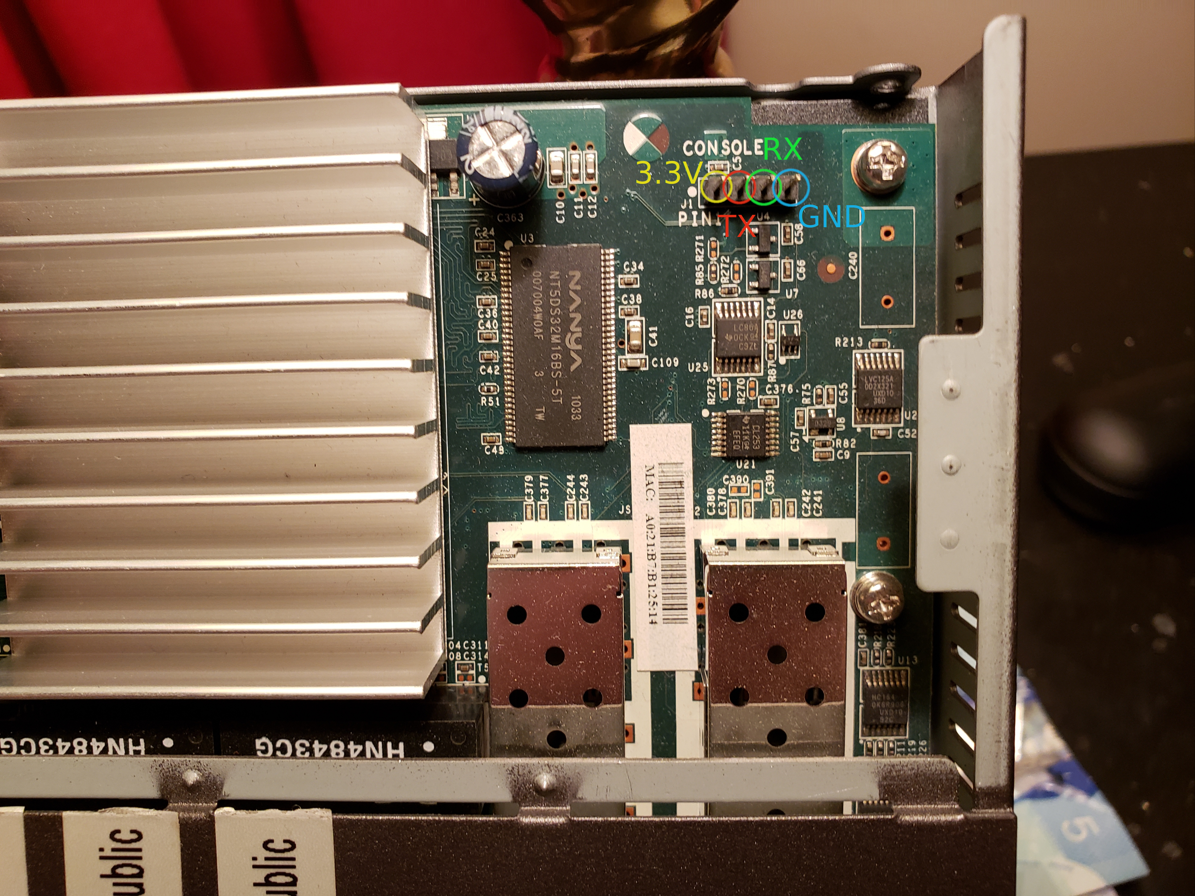
After a bit of toying around with the scope, I was able to successfully decode the pinout of the serial console on the motherboard, it is as follows:
Pin 1: 3.3V
Pin 2: TX
Pin 3: RX
Pin 4: Ground
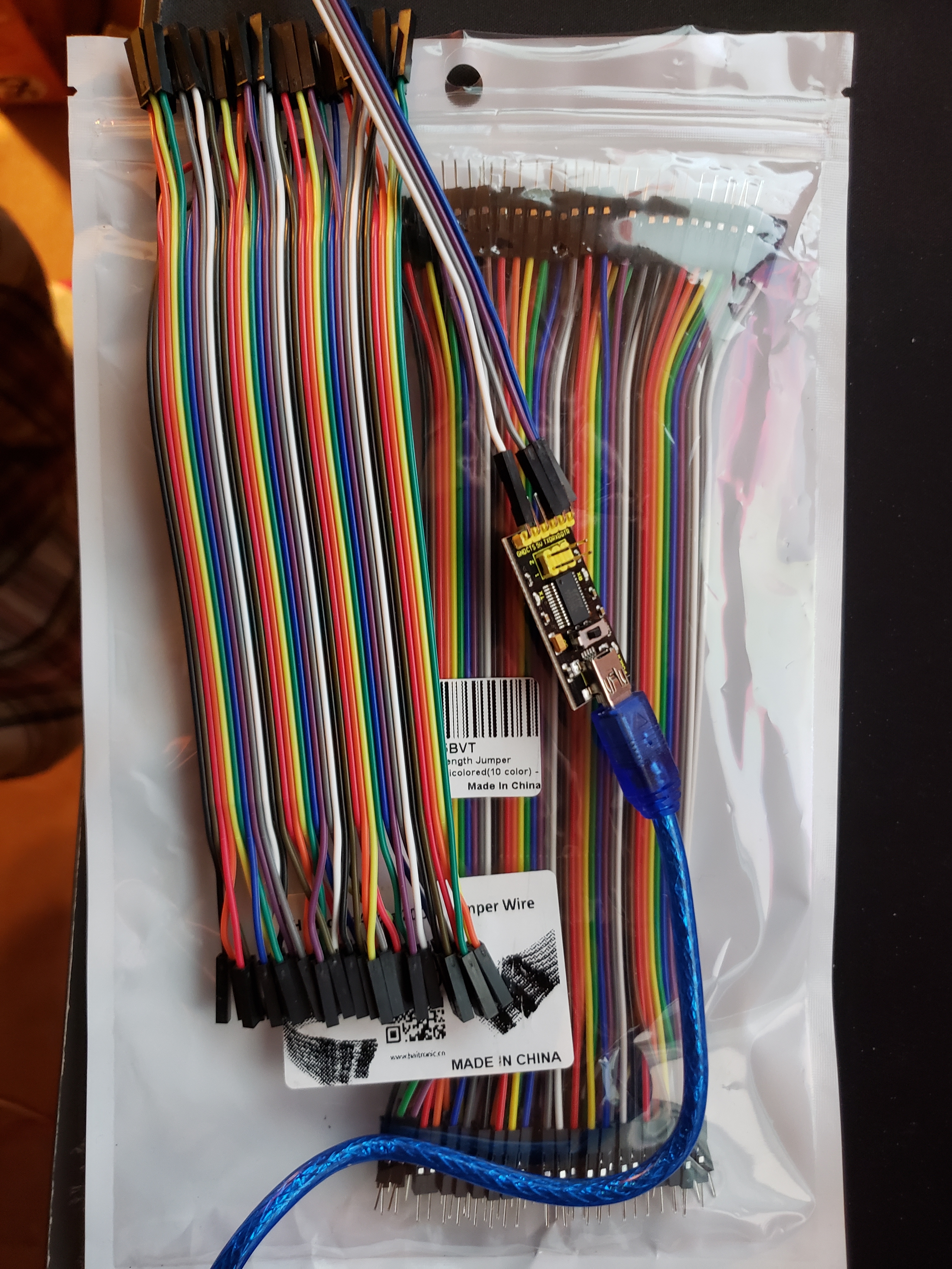
Now I didn’t have a USB to TTL serial adapter on hand back at home so I ordered one on Amazon which came the next day.
I hooked up a USB to TTL serial adapter to the console pins on the switch by connecting the adapter’s TX pin to the switch’s RX pin, connecting the adapter’s RX pin to the switch’s TX pin and connecting both grounds together. I then connected to the serial port on my computer using screen (9600baud 8N1 settings). Upon plugging in the switch, I was immediately presented with the switch’s bootloader console!
I could immediately see that the switch wasn’t booting because I got the following message for each “slot” it attempted to boot from, indicating that both images I had flashed on the switch were somehow corrupt. Very weird since they came directly from Netgear’s site…
Loader:elf Filesys:raw Dev:flash0.os1 File: Options:(null)
Loading:
Validating the code file...
Flash image is 4196278 bytes,  CRC 00006A5F
Flash image size is bogus!
Failed.
Could not load flash0.os1:: File not found
nvram_commit: will write 160 bytes from 83f00a64
I was then dumped to a CFE> prompt where I was unsure how to proceed. I did a bit of googling and found a blog post where someone else was going through the same process I was with a different netgear product and provided the bootloader command to flash a new firmware file via TFTP. The command looks something like flash -noheader <TFTP_SERVER_IP>:<FIRMWARE_FILENAME> flash0.os (flash0.os is “slot 1” and flash0.os1 is “slot 2”). I hooked my computer up to the switch via ethernet and gave it a static IP of 192.168.0.10/24 because this particular switch’s bootloader gives a it default ip address of 192.168.0.239/24 and then quickly installed a TFTP server on my computer. I returned to the serial console and got to work:
CFE> flash -noheader 192.168.0.10:GS108Tv2_GS110TP_V5.4.2.33.stk flash0.os
Reading 192.168.0.10:GS108Tv2_GS110TP_V5.4.2.33.stk: Done. 4196342 bytes read
Programming...
After quite some time (5 minutes for a 4MB firmware file…), I got this:
Programming...done. 4196342 bytes written
nvram_commit: will write 174 bytes from 83f01560
result 174 (372)
nvram_commit: will write e8 bytes from 83f0172c
result e8 (232)
*** command status = 0
Looks like this worked! I rebooted the switch and immediately hit a brick wall when I found myself facing the exact same error messages as before. Something was definitely wrong with this switch and not with the firmware file so I got back to googling. This Netgear forum thread seems to suggest that there was in fact a (completely undocumented in the latest firmware’s release notes) firmware “update laddering” procedure required. Meaning that it wasn’t supposed to be possible for me to upgrade from a 2010 firmware right to a 2018 firmware file without upgrading to an intermediate firmware. I was very disappointed to have learned about this on a community forum AFTER having bricked my switch but I digress.
I didn’t feel like upgrading to every single firmware file out of like 15 firmware revisions considering it took at least 5 minutes to flash every time so I just looked at the version numbers. I noticed at some point in time that there was a huge firmware numbering jump from 5.0.5.10 to 5.4.2.11 so I told myself that there had to be a major change in between those two firmware revisions. I snagged a copy of version 5.0.5.10 and TFTP’d it over to the switch using the same command as before. This time, as part of the flashing process I noticed some additional output on the bootloader console:
ramfs crc OK (0xa2b355f7)ramfs
...................................................................
Updating boot code
Current version   MAJ 5 MIN 1 BLD 0 REL 1
Updating version  MAJ 5 MIN 1 BLD 0 REL 2
........
Boot code upgrade successful

Reference platform resetting ...
It looks like this firmware package not only contained an operating system upgrade but also upgraded the switch’s bootloader from version 5.1.0.1 to 5.1.0.2. This was an immediate flag as to why the switch wasn’t able to boot 2018 firmware in its current state, the bootloader was out of date. (Come on Netgear, couldn’t you have provided this bootloader update with all versions of the operating system that required it!???)
After flashing this firmware and rebooting the switch, it was finally back alive and I had never been so happy to see the switch’s web gui! I remembered that the latest version of the firmware was still installed in the second “slot” so I used the gui to make that “slot” active and rebooted the switch once again.
This time, on the serial console I was able to see the following while the switch booted:
..FastPATH software Version 5.4.2.33 Build Date: Fri Sep 7 05:17:51 EDT 2018
The GS110TP was finally unbricked, back alive and kicking on the latest firmware revision. I just have a lot of excess wiring left over from my amazon order…
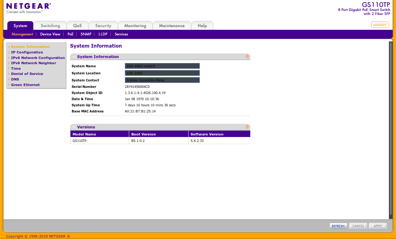
Final picture of the web gui on the latest version of the firmware.